EQUIPMENT & CAPACITY
JF-V1200 Vertical Machining Center
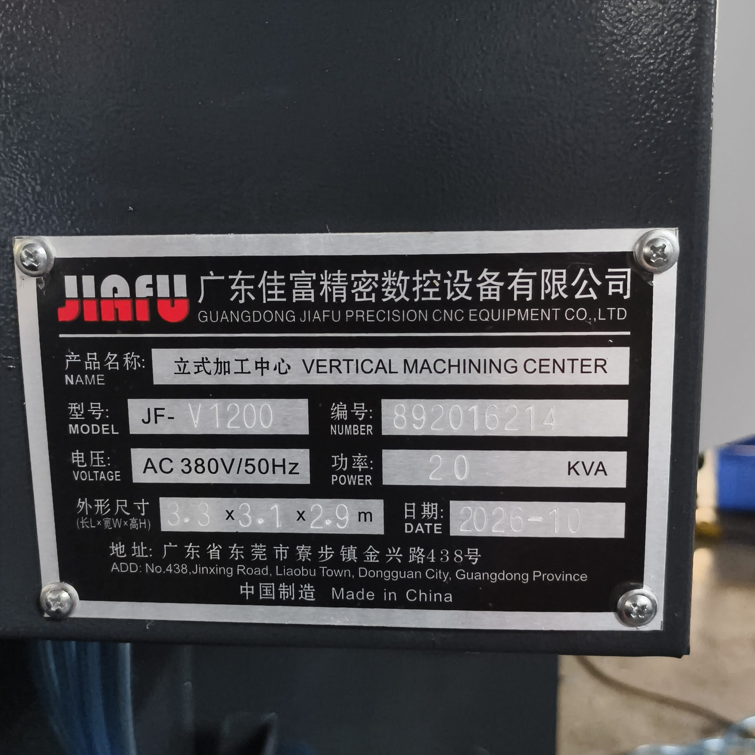
This page documents the JF-V1200 three-axis vertical machining center shown in our equipment photographs. The machine model is confirmed by its nameplate, while the capacity figures below are taken from the manufacturer’s technical proposal. Every part is still reviewed for material, geometry, workholding, tool access and inspection requirements before quotation.
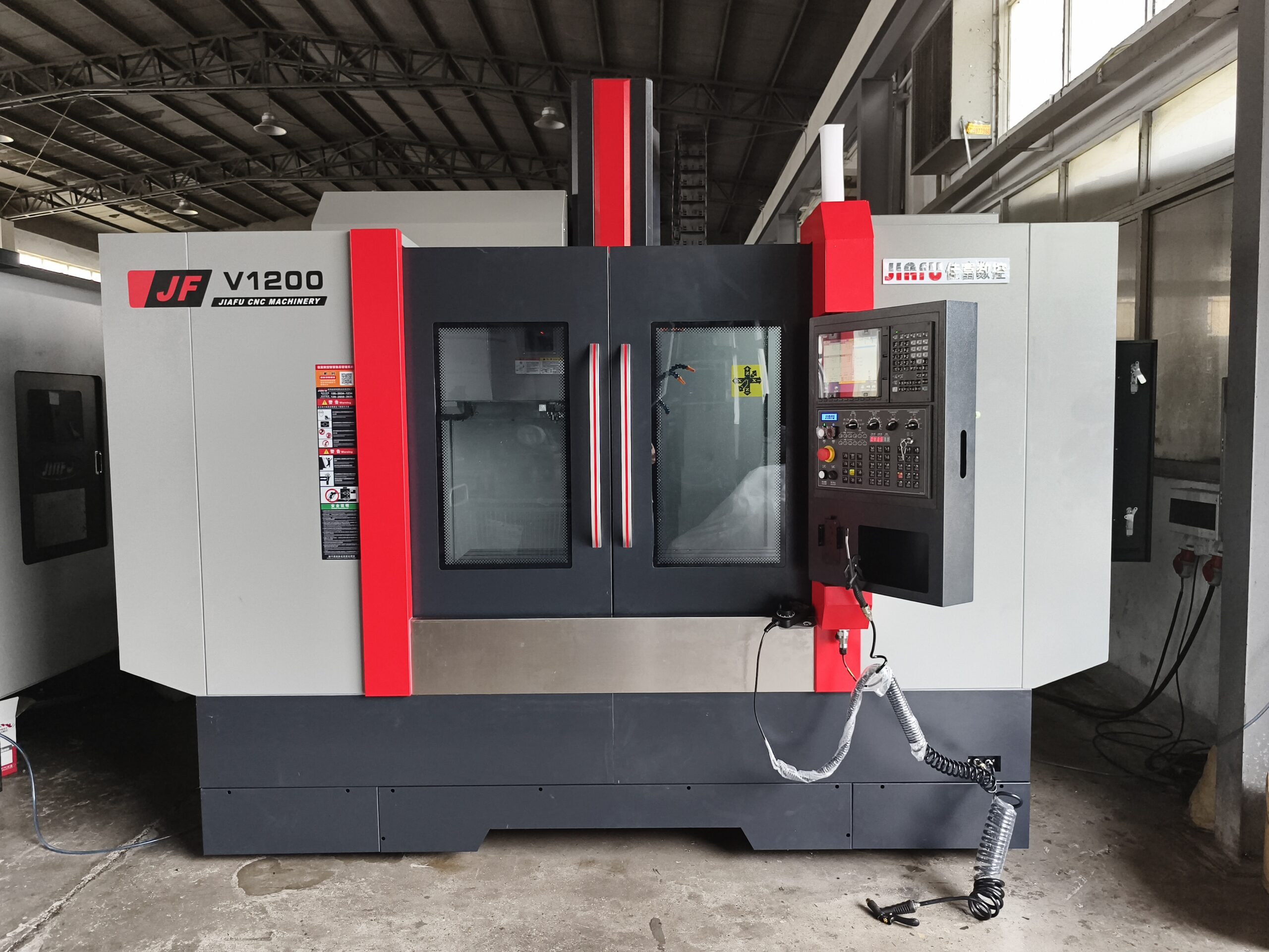
Verified Machine Configuration
| Item | Manufacturer-supplied specification |
|---|---|
| Controller | Mitsubishi M80V |
| X / Y / Z travel | 1200 / 600 / 600 mm |
| Table size | 1400 x 600 mm |
| Maximum table load | 800 kg |
| Spindle | BBT40 direct-drive spindle, 11 kW, 12,000 rpm |
| Rapid feed | 48 m/min on X, Y and Z |
| Tool storage | 24-station carousel configuration |
| Linear guideways | Heavy-duty roller linear guides on X, Y and Z |
| Coolant flow | 50 L/min |
| Machine footprint | 3300 x 2900 x 2900 mm |
| Machine weight | 6800 kg |
These values describe the configured machine in the supplied technical documentation. Usable part size can be lower after fixtures, clamps, tool clearance and inspection access are considered.
Machining Envelope
The 1200 x 600 x 600 mm axis travel and 1400 x 600 mm table support review of larger plates, housings, fixtures, manifolds, tooling components and other prismatic parts. Final feasibility depends on stock size, clamping positions, tool reach and the number of required setups.
Three-Axis Milling Work
The machine is reviewed for faces, pockets, slots, hole patterns, counterbores, threads and related milled features. Features on multiple sides may require planned reorientation and dedicated workholding. Compare straightforward, indexed and simultaneous multi-axis approaches in our 3-axis vs 5-axis CNC machining guide.
Machine Accuracy and Part Tolerances
The manufacturer’s proposal states positioning accuracy of +/-0.005 mm per 300 mm and repeatability of +/-0.003 mm to its referenced JIS criteria. These are machine specification values, not automatic guarantees for every finished component.
Part tolerance capability also depends on material, feature size, wall thickness, thermal behavior, stock condition, tool reach, workholding, setup count and inspection method. Critical dimensions must be identified on the drawing and reviewed before production. See our CNC machining tolerances and inspection guide and quality and inspection page.
Workholding and Setup Review
Send the current drawing and matching 3D model so datums, clamping surfaces, tool access and setup sequence can be reviewed. The nominal travel is not the same as the maximum guaranteed finished-part envelope.
Materials and Finishes
We review aluminum, stainless steel, steel, copper alloys, titanium and engineering plastics within our confirmed material scope. View the exact grades and confirmed surface treatments in our materials and finishes center.
JF-V1200 Machine Identification
What to Send for Capacity Review
- Current 2D drawing and matching 3D model
- Material grade and stock condition
- Required quantity and revision
- Critical dimensions, fits, threads and datums
- Surface finish and cosmetic requirements
- Inspection reports or material records required
- Delivery destination
Review Your Part for the JF-V1200 Work Envelope
Send the drawing, model, material, quantity and inspection requirements. We will review the actual setup and tool-access requirements before quoting.