The 3-axis vs 5-axis CNC machining decision is not a matter of selecting the machine with the largest number of axes. The best process is the one that can reach the required features, maintain the required relationships and produce the part with a controlled setup and inspection plan.
This guide compares 3-axis machining, 3+2 indexed machining and simultaneous 5-axis machining. It also explains the geometry, tool access, workholding, quantity and quality requirements that should drive the decision.
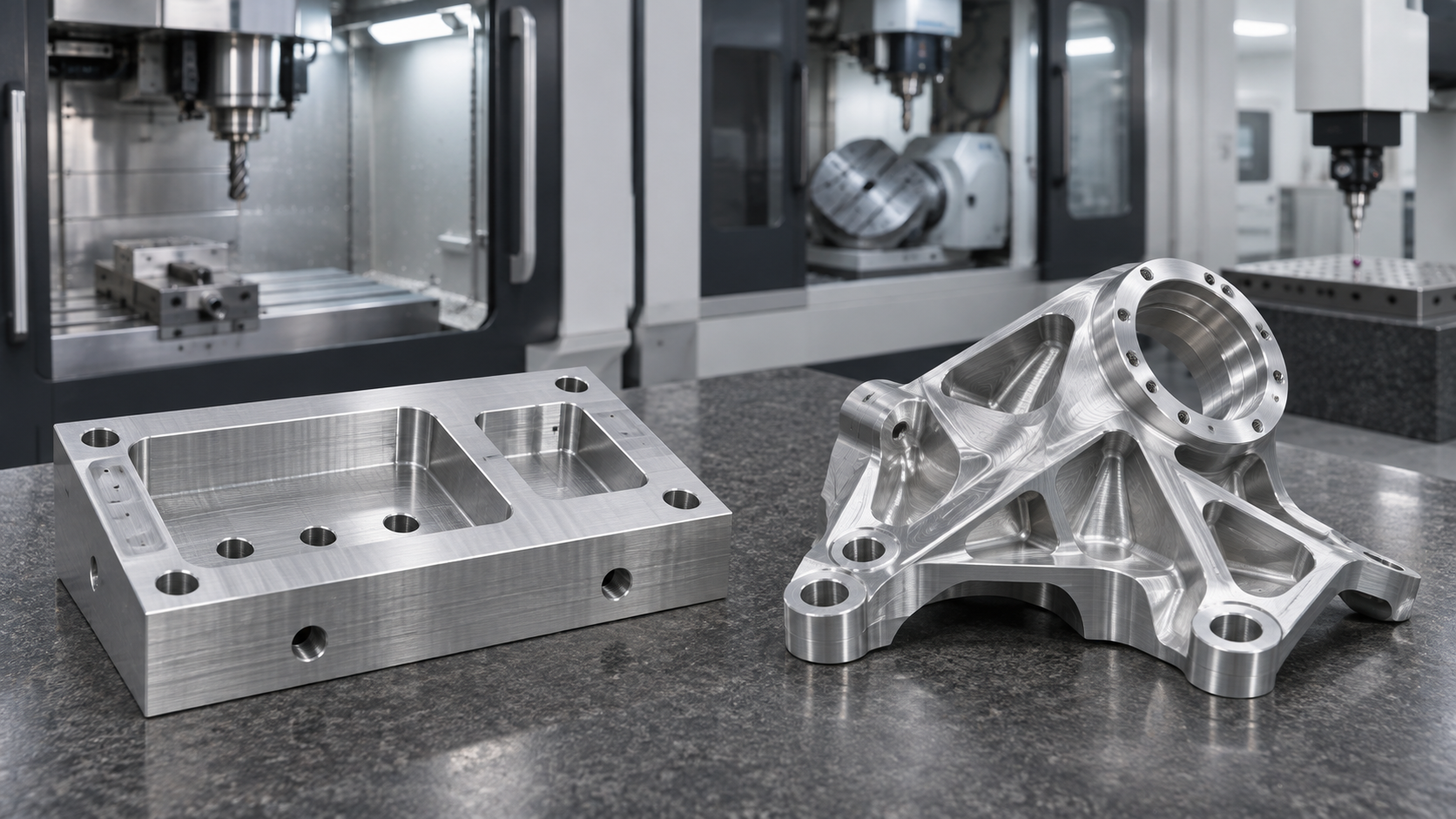
Quick Answer: 3-Axis or 5-Axis CNC Machining?
Use 3-axis machining when the important features can be reached from one or more straightforward orientations and the required setups can be controlled reliably. It is often the practical choice for plates, housings, brackets, pockets, slots and many prismatic components.
Consider 3+2 or 5-axis machining when a part has multiple angled faces, features that are difficult to reach, closely related features on several sides or contoured surfaces that would otherwise require complex fixtures and repeated repositioning.
More axes do not automatically produce a better part. The drawing, geometry, datum strategy, machine configuration, tool access, workholding and inspection plan must be reviewed together.
In short, the 3-axis vs 5-axis choice should follow the part requirements rather than the axis count alone.
What Is 3-Axis CNC Machining?
A 3-axis milling machine moves the cutting tool relative to the workpiece along the X, Y and Z linear axes. During a machining operation, the tool approaches the part from a fixed spindle direction.
Features on other sides can still be machined. The part is removed, reoriented and located again in another setup, or it is held in a fixture designed to expose the required face.
3-axis machining is commonly suitable for:
- flat plates and mounting surfaces;
- pockets, slots and counterbores;
- hole patterns approached from a common direction;
- simple housings and rectangular brackets;
- prototypes and production parts with accessible features;
- parts where separate setups do not compromise critical feature relationships.
The important question is not whether a part has features on several sides. It is whether those features can be located, machined and inspected through a stable and economical setup plan.
What Is 3+2 Indexed Machining?
In 3+2 machining, two rotary axes position the workpiece or tool at a selected angle. The rotary axes are then held fixed while cutting occurs with the three linear axes.
This is also called positional, indexed or fixed-axis machining. It can expose angled faces without requiring a separate manual fixture for every orientation. It may also allow a shorter tool to reach a feature more directly.
3+2 machining should not be described as simultaneous 5-axis cutting. The distinction matters because the machine motion, programming method, collision review and suitable geometries are different.
What Is Simultaneous 5-Axis Machining?
In simultaneous 5-axis machining, the linear and rotary axes can move together during the cutting operation. The tool orientation can change continuously relative to the surface.
This capability can be useful for:
- complex freeform or contoured surfaces;
- impeller-, blade- or turbine-like geometry;
- deep or angled features that benefit from controlled tool orientation;
- multi-face parts where feature relationships favor fewer repositioning operations;
- geometries that require continuous changes in tool angle.
Simultaneous motion also creates additional programming, simulation, workholding and collision-control requirements. It is justified when the geometry and manufacturing plan benefit from it, not simply because the machine has five axes.
3-Axis vs 5-Axis CNC Machining: 3+2 Included
| Decision factor | 3-axis machining | 3+2 indexed machining | Simultaneous 5-axis machining |
|---|---|---|---|
| Cutting motion | X, Y and Z linear motion | Rotary axes position the part; cutting occurs with the rotary axes fixed | Linear and rotary axes can move together while cutting |
| Feature access | Best for features accessible from straightforward orientations | Useful for multiple faces and fixed angled features | Useful for continuously changing tool angles and complex surfaces |
| Repositioning | May require additional manual setups | Can reduce manual reorientation for suitable parts | Can reduce repositioning for suitable complex geometry |
| Workholding | Often simpler, but each setup must locate the part correctly | Rotary clearance and fixture access must be checked | Fixture, machine limits and collision zones require detailed review |
| Programming | Usually more direct | Requires indexed-axis planning and verification | Requires more advanced toolpaths, simulation and verification |
| Typical cost drivers | Number of setups, fixtures, tools and inspection steps | Rotary setup, programming, access and verification | Programming, simulation, machine time, tooling, risk and inspection |
| Best fit | Accessible prismatic parts and controlled multi-setup work | Multi-face or angled features that can be cut from fixed orientations | Complex contours or features needing changing tool orientation |
This comparison is a selection guide, not a guaranteed process route. The correct method depends on the individual part.
When 3-Axis Machining Is the Better Choice
3-axis machining may be the stronger manufacturing choice when:
- the part is mainly prismatic;
- critical features are accessible from one direction;
- additional orientations can be located from clear datums;
- standard workholding provides sufficient rigidity;
- the expected quantity supports a simple, repeatable fixture;
- complex rotary motion would add cost without improving the result.
A well-planned 3-axis process can be efficient, repeatable and easier to inspect. Selecting 5-axis equipment for an accessible part does not remove the need for correct datums, suitable tools, stable workholding and dimensional verification.
Explore the published CNC milling service for an overview of SYD Precision’s milling workflow.
When 5-Axis Machining May Be Justified
3+2 or simultaneous 5-axis machining may be justified when:
- holes or faces are located at several compound angles;
- a part has difficult tool-access zones or deep features;
- several critical features must maintain a close relationship across different sides;
- a shorter, more rigid tool orientation can reduce reach-related problems;
- a contoured surface requires changing tool orientation;
- repeated manual setups create unacceptable complexity or risk.
The word “may” is important. A process engineer must still review the machine’s usable travel, rotary limits, fixture position, spindle and holder clearance, tool length, stock shape and probing or inspection approach.
For a current equipment overview, see CNC machining equipment and capacity. Final process selection remains drawing-specific.
Fewer Setups Can Help, but One Setup Is Not a Guarantee
Reducing manual re-fixturing can remove some opportunities for locating error and can simplify relationships between features machined in the same controlled setup. However, “one setup” is not automatically the lowest-risk plan.
The part may still require:
- a second operation to remove holding stock;
- access to the clamped face;
- soft jaws or a dedicated fixture;
- probing or datum transfer;
- distortion control between roughing and finishing;
- intermediate or final inspection outside the machine.
The setup count should therefore be evaluated together with workholding, deformation, accessibility and inspection—not used as a marketing number by itself.
More Axes Do Not Automatically Mean Tighter Tolerances
Axis count is only one part of the manufacturing system. Accuracy and repeatability are also affected by:
- machine condition and calibration;
- spindle, holder and tool runout;
- tool length and cutting forces;
- material stability and heat;
- fixture rigidity and datum definition;
- rotary-axis positioning and kinematic compensation;
- probing, measurement strategy and environmental control.
A 5-axis toolpath cannot correct an ambiguous drawing, unstable workholding or unsuitable inspection plan. Critical dimensions and geometric controls should be reviewed feature by feature.
Read the CNC machining tolerances and inspection guide when preparing dimensional requirements.
How the Process Choice Affects Cost
The cost difference is not determined by machine rate alone. A useful 3-axis vs 5-axis comparison includes:
- programming and toolpath verification;
- number and complexity of fixtures;
- manual setup and datum-transfer time;
- cutting tools, holders and required reach;
- machine cycle time;
- simulation and collision-review effort;
- in-process and final inspection;
- expected quantity and repeatability requirements;
- risk of scrap, rework or distortion.
A complex part may cost less on a multi-axis route if it eliminates several difficult fixtures and reduces handling. A simple part may cost more if 5-axis programming and machine time add no functional benefit.
See CNC Machining Cost: 9 Factors That Affect Your Quote for a broader quotation breakdown.
Design Checklist Before Requesting a Quote
- Which features are functionally critical?
- Which datums control those features?
- Can the cutting tool reach each surface with adequate holder clearance?
- Are any holes, threads or faces located at compound angles?
- Does the part contain deep cavities, undercuts or freeform contours?
- Which surfaces will be used for workholding?
- Can the part tolerate re-clamping between operations?
- Are tolerance and inspection requirements defined on the 2D drawing?
- Does the surface treatment affect datums or final dimensions?
- What quantity and repeat-order plan are expected?
Provide a dimensioned 2D PDF and a matching 3D STEP file whenever possible. Include the material, quantity, finish and critical tolerance requirements.
How SYD Precision Reviews 3-Axis and Multi-Axis Parts
SYD Precision reviews the drawing and model before confirming a machining route. The review considers feature access, datum strategy, stock form, workholding, tool reach, material behavior, quantity, surface treatment and inspection requirements.
The proposed operation sequence may use a straightforward 3-axis route, indexed positioning or another suitable multi-operation plan. The final recommendation is project-specific and should be confirmed during quotation and technical review.
Request a CNC Machining Review
Send the latest files and identify the dimensions or feature relationships that matter most. The review is more useful when it includes:
- dimensioned 2D PDF drawing;
- matching 3D STEP or STP model;
- material grade and condition;
- prototype and production quantities;
- surface treatment and cosmetic zones;
- critical dimensions, GD&T and inspection documentation;
- delivery location and packaging requirements.
Frequently Asked Questions
Is 5-axis CNC machining always more accurate than 3-axis machining?
No. Axis count alone does not determine part accuracy. Machine condition, setup, tooling, material behavior, datum control and inspection all affect the result.
Can a 3-axis machine produce features on several sides?
Yes. The workpiece can be reoriented in additional setups. The manufacturing review determines whether those setups can maintain the required feature relationships efficiently.
Is 3+2 machining the same as simultaneous 5-axis machining?
No. In 3+2 machining, the rotary axes position the part and remain fixed during cutting. In simultaneous 5-axis machining, linear and rotary axes can move together during the cut.
Does 5-axis machining always reduce cost?
No. It may reduce fixtures and handling for suitable complex parts, but programming, simulation, machine time and inspection can add cost. The complete process plan must be compared.
What files are needed to choose the machining method?
A matching 3D STEP model and dimensioned 2D PDF drawing are recommended. Add material, quantity, finish, critical tolerances and inspection requirements.